
输出终端出现过载电压时,合理的方法是将放大器输出节点与输出终端分离一段时间。依靠音频功率放大器中的机电继电器,有经验的工程师已使用这种串联分离,但出于不同原因:扩音器保护。 SSR (固体继电器)包括optoeleCTRonIC、photovoltaic、OptoMOS和PhotoMOS设备,由于控制和负载管脚之间的电隔离,在适度电流水平上满足负载分离任务(参考文献3)。
图3的串联保护电路,使用串联高压SSR分离放大器输出终端。输出电压增加到正参考电压限以上或降到负参考电压限以下,通过AND逻辑器件IC5,引起IC2或IC3比较器改变其输出状态,并关闭SSR IC4。图4显示实现这个方法的简单电路。

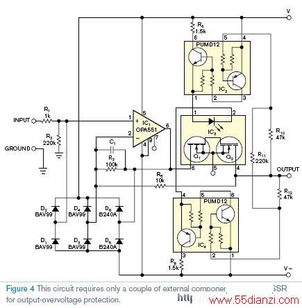
图4电路只需要一对外部器件,用SSR实现输出过电压保护。增加过电压关闭IC2中的电阻,通过IC3的控制LED中断电流流动。继电器IC3断开,保护放大器和钳位二极管。无论是否存在内部电流保护,电路用Clare、Matsushita Electronic Works和Panasonic SSR测试。供电电源采用±15V;R10、R11和R12设置触发点为±16V。省略R11偏移触发点到±14.5V。保护电路操作下,带0.5V过电压保护的SSR断开延时100到200µs,更高的过电压延时时间稍有减小。注意到,通过钳位二极管,电流峰值比带低电阻SSR更高。
英文原文:
Circuits protect outputs against overvoltage
Adding a solid-state relay and control circuitry to an amplifier's output provides overvoltage protection.
Dimitri Danyuk, Kiev, Ukraine; Edited by Charles H Small and Fran Granville -- EDN, 10/11/2007
In test-and-measurement applications, you must provide overvoltage protection for the output terminals of
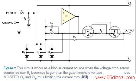
amplifiers, power supplies, and similar components. The conventional way to aCComplish this task is to add series resistors with the output node along with the clamPINg diodes to power-supply rails or other threshold voltages (Reference 1 and Figure 1). This resistor signifiCANtly reduces current-output capability and the output-voltage swing with low-resistance loads. The aLTErnative approach is to use fuses or other current-limiting devices, which precede these clamps’ high energy-absorption capability. The circuit in Figure 2 works as a bipolar current source when the voltage drop across source resistor R6 becomes larger than the gate-threshold voltage of depletion-mode MOSFETs Q1 and Q2, thus limiting the current through the clamping diodes (Reference 2). The drawback of this approach is high power disSIPation on series components during the overload condition.
A reasonable approach disconnects the amplifier-output node from the output terminals for the period when the overload voltage exists on output terminals. Engineers for decades have used such serial disconnection by means of eleCTRomechanICal relays in audio power amplifiers but for a different reason: louDSPeaker protection. SSR s (solid-state relays), inc luding optoelectronic, photovoltaic, OptoMOS, and PhotoMOS devices, suit the task of load disconnection at moderate current levels because of galvanic isolation between the control and the load PINs (Reference 3).
The series-protection circuit of Figure 3 disconnects the amplifier-output terminal using a series-connected, high-voltage SSR. Raising the output voltage above the positive-reference-voltage or below the negative-reference-voltage threshold causes either the IC2 or the IC3 comparator to change its output state and turn off SSR IC4 through AND logic element IC5. Figure 4 shows the simple circuit realization of this approach.
The circuit in Figure 4 requires only a couple of external components to use an SSR for output-overvoltage protection. Rising overvoltage turns off both transistors in IC2, interrupting current flow through the control LED of IC3. Relay IC3 opens, protecting the amplifier and clamping diodes. The circuit was tested with a handful of Clare, Matsushita Electronic Works, and Panasonic SSRs with and without internal current protection. The power-supply rails are ±15V; R10, R11, and R12 set the triggering levels and are equal to ±16V. Omitting R11 shifts the triggering levels to ±14.5V. The SSR turn-off delay in protection-circuit operation is 100 to 200 µsec for relays with 0.5V overvoltage protection and becomes slightly shorter with higher overvoltage. Note that the peak current through clamping diodes CAN be rather high with low-on-resistance SSRs.
英文原文地址: http://www.edn.com/article/CA6486026.html
本文关键字:暂无联系方式稳压-电源电路,单元电路 - 稳压-电源电路
上一篇:UC3842电路的保护问题


