点击看原图
另外模块中的五个系数定义为常数,以节省硬件资源,并且采用0舍1入法进行数据处理,尽量提高数据运算精度。VHDL程序如下:
entity smultadd1 is
port (clk_regbt,clk_reg: in std_logic:
x0,x1,x2,y0,y1:in std_logic_vector(9 downto 0);
yout: out std_logic_vector(9 downto 0));
end smultadd1;
architecture behav of smultadd1 is
signal tan,tbn,tp2n:std_logic;
signal cnt: std_logic_vector(2 downto 0);
signal ta,tb,taa,tbb:std_logic_vector(8 downto 0);
signal tmpa,tmpb:std_logic_vector(9 downto 0);
signal tp:std_logic_vector(18 downto 0);
signal tpp:std_logic_vector,22 downto 0);
signal ytmp,p:std_logic_vector(23 downto 0);
constant a0:std_logic_vector(9 downto0:=“0000011100”
(其余常数说明略)
begin
tp2n<=tan xor tbn;--求补后送阵列乘法器
taa<=not ta +‘1' when (tan=‘1') else ta;
tbb<=not tb +‘1' when (tbn=‘1') else tb;
tpp<=‘1'&‘1'&‘1'&‘1'& not tp +‘1' when(tp2n=‘1') elsetp;
tmpa<=a0 when cnt=0 else
a1 when cnt=1 else
a2 when cnt=2 else
b0 when cnt=3 else
b1 when cnt=4 else (others=>‘0');
tmpb<=x0 when cnt=0 else
x1 when cnt=1 else
x2 when cnt=2 else
y0 when cnt=3 else
y1 when cnt=4 else (others=>‘0');
ta<=tmpa(8 downto 0);tb<=tmpb(8 downto 0);
tan<=tmpa(9);tbn<=tmpb(9);
tp<=taa*tbb;
p<=(others=>‘0') when (tmpb=“0000000000”) else
tp2n & tpp;
process (clk_reg,clk_regbt)
begin
if clk_reg=‘1' then cnt<=“000”;ytmp<=(others=>‘0');
elsif (clk_regbt'event and clk_regbt=‘1') then
if cnt<5 then cnt<=cnt+1;ytmp<=ytmp+p;
elsif (cnt=5) then
if ytmp(7)=‘1' then
yout(8 downto 0)<=ytmp(16 downto 8)+1;
yout(9)<=ytmp(23);
else yout(8 downto 0)<=ytmp(16 downto 8);
yout(9)<=ytmp(23); end if;
end if;
end if;
end process;
end behav;
IIR2模块的输出数据采用将补码最高符号位直接取反转换为移码后,就可以送到DAC7520实现双极性信号输出。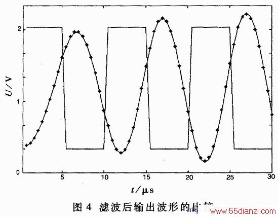
3系统性能测试
系统性能的测试采用单极性方波周期信号作为输入信号。信号的频率为100kHz,在采样频率为2MHz时,每个周期采样20个点,换算成数字域频率为0.1π,其二次谐波的数字频率为0.2π。输入到TLC5510的信号电压幅度为0~2V,则经过A/D转换后的输出为00H~FFH。由于低通滤波器的阻带截止频率选在200kHz,衰减32dB,由信号理论分析可知,周期方波信号没有二次谐波,所以对三次谐波的衰减经过IIR滤波器后输出有直流分量的基波(频率为100kHz)正弦信号。理论计算给出的方波周期信号基波幅度为:
2E/π= (2×255)/π=162.34
输入一个周期的数据,Matlab的计算值与MAX+plusⅡ的仿真值如表3所示。
表3 滤波后输出的数据

点击看原图
(160.9-162.34)/162.34=-0.87%
四阶 IIR滤波器实现的满度输出值为[282-(-31)]/2=156.5,与理论值的误差为:
(156.5-162.34)/162.34=-3.6%
这是由于有限精度算法所引起的误差,可以通过增加二进制位数来提高系统的运算精度。图4给出单极性方波信号的前三个周期经过滤波后得到的含直流分量的输出波形,其中实线为Matlab的计算值,“*”为MAX+plusⅡ的仿真输出。可见,该四阶级联IIR滤波器达到了设计要求。
如果改变滤波器的输入时钟频率,则可以改变滤波器的截止频率。另外如果输入无直流分量的周期信号,而且其频率为采样频率的1/20,则该低通滤波器可以直接得到基波分量输出。其实,要将TLC5510输出的直流分量滤出很容易,只需利用FPGA做一个减法运算即可。
本文关键字:滤波器 DSP/FPGA技术,单片机-工控设备 - DSP/FPGA技术


